The Science of Friction and Inclined
Planes
Elsa Lau | UBC PHYS 420C | 2024-25
Ramp
Construction

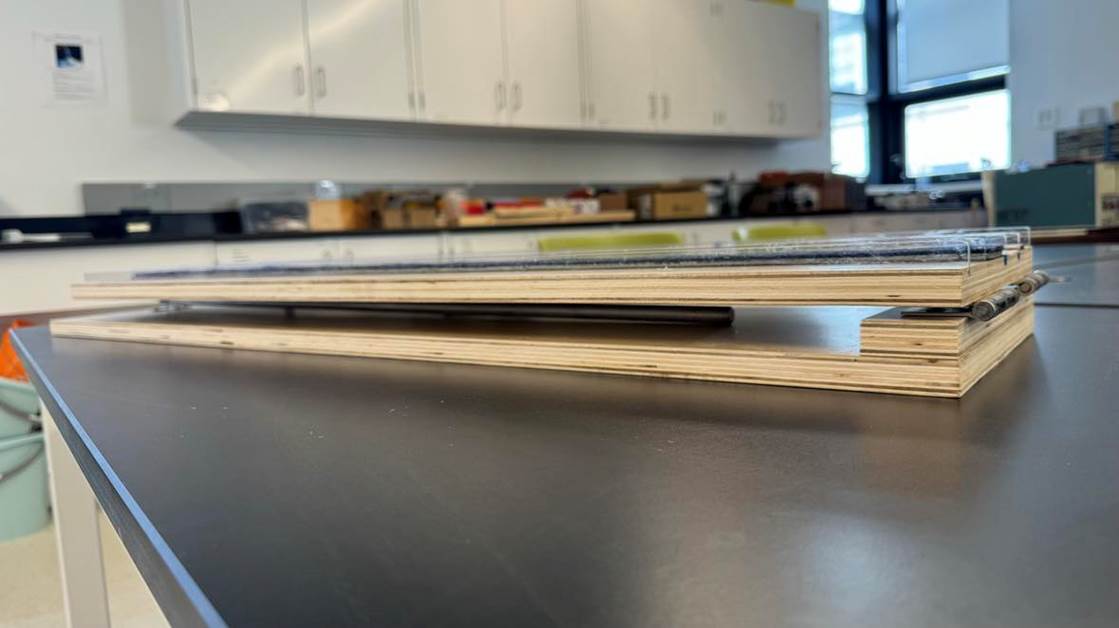
Right: Completed ramp. Left: Completed ramp, collapsed.
Depending
on the number of tracks you want to have and the masses you will be sliding
down your ramp, your dimensions will likely be different, so use this as a
guide only.
Materials
-
Wood for
baseboard: 1000mm x 257mm x 19mm
-
Wood for ramp
base: 900mm x 257mm x 19mm
-
Wood for
anchor: 45mm x 257mm x 19mm
-
Acrylic
dividers: 900mm x 3mm x 18mm (x5)
-
Metal rod:
800mm x 13mm diameter
-
3D printed slider
-
Hinges (x3)
-
Brackets (x2)
-
Screws
-
Butterfly
wing nut
-
Different
surfaces for each track of the ramp
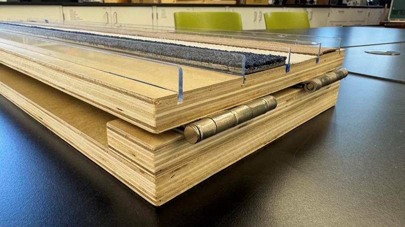
Construction
1.
Once wood is
cut to size, cut grooves approximately 6mm deep in the ramp base
wherever you want your acrylic track dividers to be. You'll want about 2mm of
wiggle room for your mass (e.g. my masses were 51mm wide, so each track was
53mm wide). Also leave some room between the edges of the ramp base and the
outermost dividers (I left 15mm).

2.
Screw the
baseboard, ramp base, anchor, and hinges together as shown.
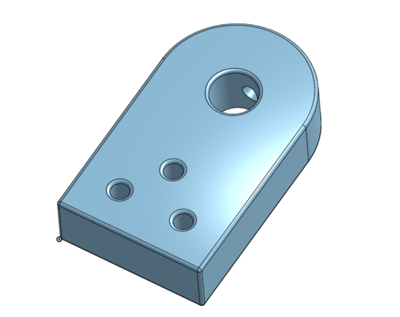
3.
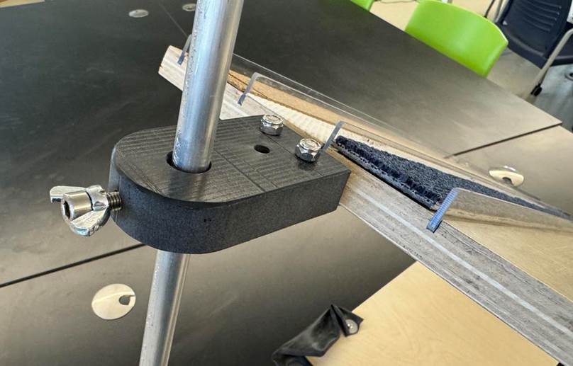
Design a
slider to be 3D printed. It will need to fit the final hinge, the metal rod,
and butterfly wing nut. This is what allows you to adjust the angle of the ramp
and keep it in place. It might look something like this:
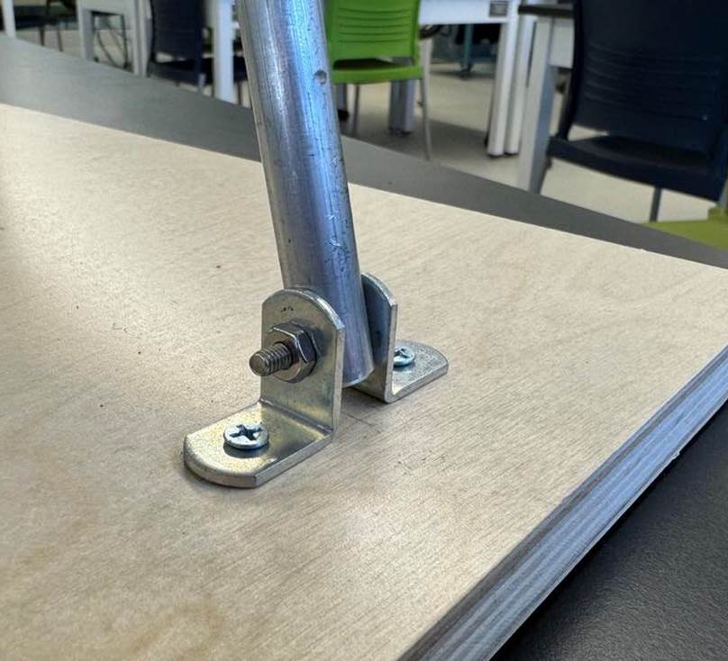
4.
Fix the metal
rod in place with the brackets on the baseboard as shown.
5.
Use the final
hinge to attach the slider to the bottom of the ramp base. Make sure it lines
up with the metal rod.
6.
Tape or glue
different materials to the surface of each track. I used cork, carpet, and rubber,
and left the last track as wood. Ensure the track is still flat, or this will
interfere with the demo. Recommended: stick different materials to the surface
of the masses you intend to slide down the ramp as well.
